Simple Techniques Used to Eliminate Corona in Connectors and Cable Assemblies
Co-authors: Val C. Robinson, Al M. Mocek, P.E.
 In choosing connectors or cables for high voltage and high reliability applications there are certain characteristics that buyers, engineers and quality control personnel should look for. This paper illustrates some of the simple corona reducing design techniques that can improve the overall performance and quality of connectors and cable assemblies.
The large quantity of existing connector and cable designs make it very difficult for the engineer to make a good choice when faced with selecting solutions for high reliability applications. Many of the high reliability applications involve high voltage and today it is often common practice to consider high voltage and corona resistant as synonymous. These high voltage, corona resistant applications will be the main consideration of this paper.
It is an established fact that corona is the ionization of air within a dielectric or adjacent to the surface of a dielectric. Ionization of that air has a twofold detrimental effect. It can degrade the dielectric to the point of electrical breakdown and it can set up transient currents in conductors that cause radio interference. It can be seen then that it would be advantageous to select designs that are corona resistant up to operating voltage levels. Since corona is the ionization of trapped air, better designs will incorporate methods of eliminating the presence of air or nullifying the effect of air that cannot be removed. There are several simple design techniques used to reduce corona discharges. Being familiar with them may aid in a difficult decision and prevent a possible failure in a critical situation.
Cable
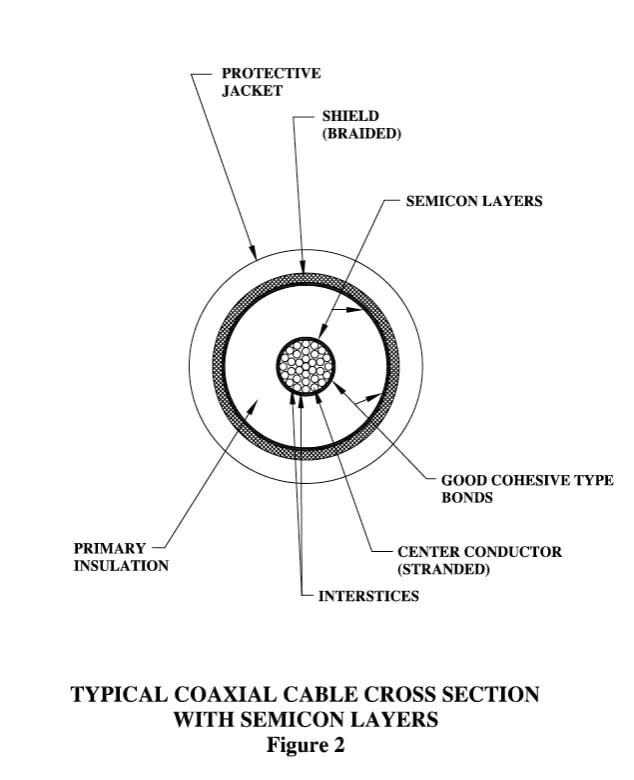
 Most high voltage applications where corona is a consideration utilize coaxial type cable. That is, cable consisting of a center conductor, primary insulation, a braided shield and a protective jacket. A typical coaxial cable cross section, depicting these components, is shown in Figure 1. This will be the only type of cable discussed herein although the principles apply to multiconductor and triaxial cables as well.
The most common center conductor utilized in coaxial cables is the stranded type. As can be seen in Figure 2, the natural lay of the individual strands creates many interstices which act as air traps making it virtually impossible to eliminate all air during the insulation extrusion process. The capability of the cable can be vastly improved by extruding a semi-conducting (hereafter referred to as semicon) layer around the center conductor as shown in Figure 2. This material is called semicon because it is not a true conductor or a true insulator. The main purpose of the semicon is to provide a uniform surface for bonding to the primary insulation during the extrusion process. The two materials are chosen for compatibility and proper process control will produce a good cohesive bond with no air voids. The minimal conductive properties of the material make it equal in voltage potential to the center conductor when the two are in intimate contact. The fact that the semicon is at the same voltage potential as the center conductor eliminates the effect of the air in the center conductor. The same semicon material is used between the shield crevices. (Refer to Figure 2).
The theory behind providing a good bond to the primary insulation indicates that polyethylene and teflon type cable do not lend themselves to good corona resistant design because of the difficulty in obtaining a bond to that type of insulation.
Connectors
corona resistant cable by itself will not provide high reliabilities. It is essential that the corona resistant cable be combined with compatible termination processes so that a reliable corona resistant cable assembly will result. There are several termination techniques used to eliminate corona and the following is a brief description of their characteristics.
Shield Termination
It is advantageous to terminate the shield in a manner that will cover all the sharp ends to prevent them from emitting electrical discharges. This can be accomplished in a manner similar to that illustrated in Figure 3.
Semicon Removal
 The semicon layer under the shield must be removed to provide adequate distance between it and the high voltage potential of the center conductor. This is usually accomplished by special techniques developed for removing the semicon layer from the primary insulation.
Molded Configuration
The most advantageous way to eliminate air in the termination area is to mold the dielectric material to the prepared cable end. The molding process is preferred because good cohesive bonds are obtained when using compatible elastomeric dielectric materials. Although it is not necessary, occasionally a pre-molded semicon bushing is added over the contact to provide a better surface for bonding. A typical semicon bushing is shown in Figure 3. Elastomer-to-elastomer bond joints are superior to elastomer to metal bond joints and will better resist above normal operating requirements such as a combination of high and low temperature extremes.
Molded Body to Shell Fit
It is important that a good fit be provided between the molded elastomer body and shell because air can become easily entrapped in this area and cause corona.
However, certain applications do require additional design considerations in this area and semicon layers have been added to the outer surface of the elastomer to negate the effect of the air void. Special consideration would be an extreme low temperature operating environment where the elastomer could shrink away from the shell due to its higher coefficient of thermal expansion.
Sharp Corners
Sharp corners are good electric discharge generates and all good designs will indicate that special consideration has been given to their removal.
Molded configurations are far superior to field assembly type units because it is impractical to consistently eliminate all of the air between the cable end and insulator when assembled mechanically.
Connector Interface
One of the most critical areas in connector design is the interface between plug and receptacle. Air must be eliminated at this junction to make the connector corona resistant. A simple method of achieving this is shown in figure 4. A tapered “tower” is used on one of the mating halves and a matching tapered “cavity” on the other. It can easily be seen that the matching tapered surfaces will make contact at the end of the tower first and a gradual pushing together of the two halves will force the rubber tower to conform to the mating cavity surfaces thereby wiping out all the air from the interface. The interface pressure must be adequate to keep the faces matched perfectly.
However, one thing that must be remembered is that the elastomer acts like a liquid in that it is somewhat incompressible. This means that it must flow rather than become smaller. Also the elastomer has a rather larger coefficient of thermal expansion and any extreme high temperature will cause considerable growth. Since the elastomer is encased by the shell and compressed on the interface, any growth will increase internal pressure until the compressive strength is exceeded and a permanent set takes place or the assembly becomes self destructive and destroys itself to relieve the pressure. Good connector designs will provide means for relieving the internal pressure at high temperature and maintaining interface pressure at low temperature.
The usual method of accomplishing this is to incorporate temperature compensating springs in the design. The springs may appear in different places but their purpose is the same in that they should maintain constant interface pressure.
Conclusions
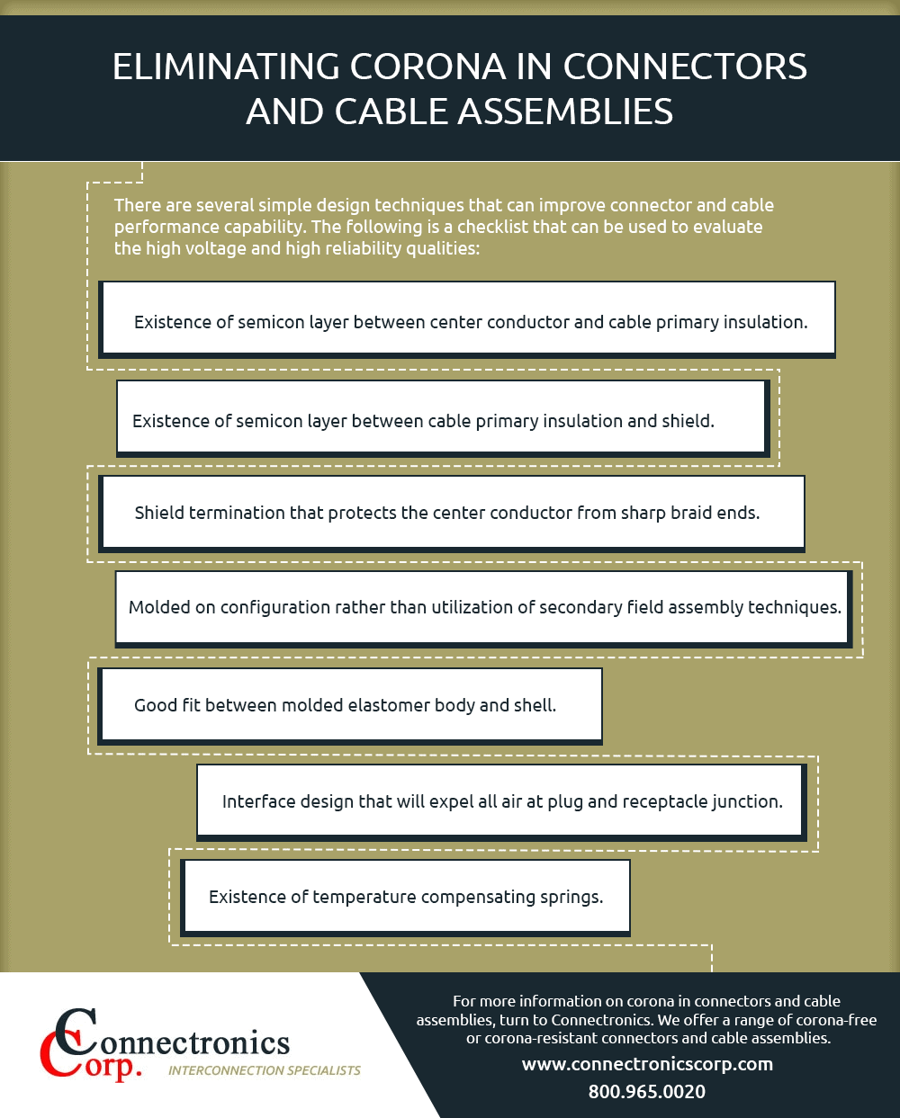
There are several simple design techniques that can improve connector and cable performance capability. The following is a checklist that can be used to evaluate the high voltage and high reliability qualities:
- Existence of semicon layer between center conductor and cable primary insulation.
- Existence of semicon layer between cable primary insulation and shield.
- Shield termination that protects the center conductor from sharp braid ends.
- Molded on configuration rather than utilization of secondary field assembly techniques.
- Good fit between molded elastomer body and shell.
- No sharp corners.
- Interface design that will expel all air at plug and receptacle junction.
- Existence of temperature compensating springs.
For more information on corona in connectors and cable assemblies, turn to Connectronics. We offer a range of corona resistant or corona-resistant connectors and cable assemblies in the following product lines:
- High Voltage Connectors
- High Current Connectors
- Underwater Cables & Connectors
- Specialized Connectors
- Wiremax – High Voltage Lead Wires
In addition, we offer engineering, design, and testing services for custom connectors. Contact us today for more information.
